CR-10 S5
Y Axis Limit Switch Problem
|
15-Dec-2017
|
|
(Click on images for a larger view)
|
|
|
The other day I attempted to print on the full 500mm x 500mm area of my S5's table. I noticed that when the print started the items being printed were quite far away from the front edge of the table. This was in comparison to what Simplify3D was showing me and it's usually pretty accurate. I let the print continue but stuck around to watch it because now I wasn't sure what was going to happen when it got to printing at the rear of the table.
Sure enough my worst fears were realized. It was printing at, pretty much on, the rear edge of the table, not like the wide spacing at the front of the table. AND it landed up hitting one of the clips that hold the glass on. Not good.
Thinking that this was a simple case of adjusting the Y Axis end stop limit switch position I set out to do that. Didn't take me long to figure out that wasn't the problem. I discovered that the limit switch was already positioned as far as it could go in the direction it needed to go to correct the situation at hand. Really not good.
Obviously realizing the table is not centered Y Axis wise I also then discovered the Y Axis did not have the full 500mm travel, it was limited to 494.1mm because of this. Maybe the ~6mm is not so bad but not being centered and printing on the edge of the table is.
Read on to see what it took to correct this problem...
|
|
|
|
|
|
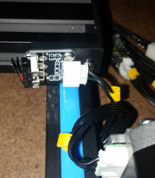
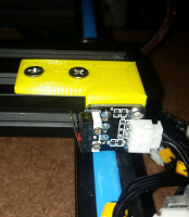
This is the position of the Y Axis limit switch
as designed and delivered by Creality. It is adjusted as far back as this bracket design will allow which is not far enongh to center the table on the Y Axis or allow the full 500mm table travel.
|
|
|
|
|
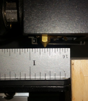
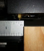
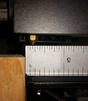
The image to the right shows the postion of the nozzle after an Auto Home is preformed and the table is sitting at the 0mm position. Note the nozzle in this 0mm Home position is 5/8" from the front of the table.
|
|
|
|
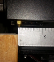
The image to the right shows the postion of the nozzle after an Auto Home is preformed and the table is moved towsards the 500mm position. I say moved towards because the actual posiion is 494.1mm. Any attempt to move closer to 500mm results in the servo/belt slipping because the table is as far phyiscally as it can go, it is stopped by/hitting the front frame. Note the position of the nozzle, it is at the rear edge of the table. The table is not centered on the Y Axis.
|
|
|
|
|
|
|
|
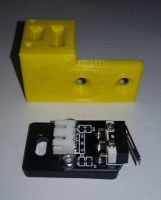
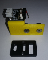
The image to the left shows the limit switch still mounted to the OEM supplied bracket and the newly designed and printed bracket behind it. Quite a difference in design.
|
|
|
|
The image to the left shows the limit switch mounted to its newly designied bracket.
|
|
|
|
|
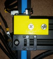
The image to the right is a side view of the newly designed Y Axis Limit Switch Bracket installed and properly adjusted for table centering and table travel.
|
|
|
The image to the right is a side view of the newly designed Y Axis Limit Switch Bracket installed and properly adjusted for table centering and table travel.
|
|
|
|
|
|
|
WARNING: One very important thing to note: The distance from the top of the aluminum extrusion the bracket is mounted on to the underside of the table carriage is very small, under 0.150" on my printer, yours may vary. The thickness of the top of the new bracket thet sits on top of the rail is 0.125". Yes not much clearance. If you are going to install this bracket on your printer make absolutely sure the carriage does not hit and/or get stopped by the bracket before powering up your printer.
|
|
|
|
|
|
The image to the left shows the postion of the nozzle after an Auto Home is preformed and the table is sitting at the 0mm position. Note that the nozzle in this 0mm Home position is now 3/16" from the front of the table.
|
|
|
The image to the left shows the postion of the nozzle after an Auto Home is preformed and the table is now moved to the 500m position. Note the nozzle in this 500mm Home position is now 3/16" from the rear of the table, just like the nozzle position when at front of the table. The table is now centered Y Axis wise and can travel the full 500mm.
|
|
|
|
|
|
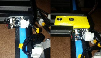
The left half of the image to the left shows the OEM bracket and limit switch when the bracket is mounted as far back as it can go. Note the position of the Limit Switch in relation to the back rail when using the OEM bracket. Now look at the right half of the image to the left and note the position of the limit switch in relation to the rear rail when using the newly design bracket. That is where the limit switch needs to be in order to allow centering the table on the Y Axis and for the full 500mm travel of the table.
Creality really screwed the pooch on this one IMO.
|
|
|
|
|
If you would like to make this bracket the STL for it is at Thingverse here.
|
|
|
|
|
|
|
|
