PETG is a bitch to get a good surface on supported surfaces, mostly due to how much it sags and especially on flat horizontal surfaces. Took me a while to master it and it's tricky.
One thing you don't want to do is use Dense Layers in Simplify3D for PETG. They work great for PLA and ABS but for PETG you're more likely to not be able to separate the supports using Dense Layers especially up in the 70 80 90% infill range.
I print a lot of PETG at a layer height of 0.3mm. When using supports you want to leave space between the last support layer and the "real" layer you're putting down. In S3D you do that by telling it how many layers to skip and the lowest you can go is 1 layer, which is then 0.3mm. That's too much. That means that the nozzle for the "real "layer is now 0.6mm above the supports when it's being laid down. Due to PETG's tendency to sag and have nothing to stick to like the trace next to it because that trace sagged too you get a miss-mashed surface finish.
So here's what I do, mind you support infill is no more then 30% and a lot of times for flat surfaces/areas 20% and no, I repeat no, Dense Layers.
For this example if you're printing at 0.3mm layers and your supported layer starts at a 3.9mm height use the Variable Settings feature and split the process at 3.3mm and again at 3.9mm, so now you have 3 processes. Set the second/middle process to print at a 0.15mm layer height.
So now the first process prints 0.3mm layers at nozzle height from 0.0mm to 3.0mm, the second process prints 0.15mm layers at nozzle height from 3.15mm to 3.75mm, then the third process goes back to printing 0.3mm layers starting with the layer at nozzle height 3.9mm onward.
What this does for you is with the second process being set for 1 layer space between the supports and the "real" layer, that space is now 0.1mm not 0.3mm, a big deal due to PETG's tendency to sag.
Now, adjust the third process so that S3D thinks that "real" layer being put down on the supports is bridging even though in reality it is supported. What this does for you is that it allows you to leverage the bridging parameters to improve putting down the first layer of the "real" layer of your supported area.
For this set the Bridging Parameters as follows:
Unsupported area threshold: [whateve is necessay]
Extra inflation distance: 2.0 mm
Bridging extrusion multiplier: 74%
Bridging speed multiplier: 75%
Use bridging infill angle: [whateve is necessay]
Apply bridging settings to parameters: Checked
For your supports "Separation From Part" *if* you are not supporting any angular surfaces set:
Horizontal Offset From Part: 1.0 mm
Upper Vertical Separation Layers: 1
Lower Vertical Separation Layers: 1
If you are supporting angular surfaces you should drop the Horizontal Offset From Part to 0.2mm but that could lead to making removal of supports that are close to vertical surfaces a little difficult.
AND set cooling to kick in the cooling fan at 100% when bridging.
Once this is all set up do a "Prepare to Print" and walk through the layers to insure that the first "real" layer being put down atop the supports is yellow indicating bridging. Even any single traces that start the layer i.e. a curved bottom wall. If it's a wall that is curved on the bottom the first traces that are the center should be yellow then the next layer the traces above them should be blue but the outside/perimeter traces should be yellow for a few layers.
Also look closely and insure the the first "real" layer is being put down atop the supports by the third process at a layer height of 0.3mm and not by the second process at a layer height of 0.1mm. You don't want a 0.1mm "real" layer being put down on a 0.1mm support layer, that can lead to them bonding together too well. You want a fat 0.3mm "real" layer put down on the 0.1mm support layer, this will help in separation.
A 0.1mm layer being put down instead of the 0.3mm wanted layer can happen due to slicer rounding because... That supported layer really should be at 3.78mm high which is closer to 3.9mm high then it is to 3.6mm high, the two choices where the slicer could put it. So it chose 3.9mm high. But now since you're printing those layers at a 0.1mm height it can put that layer down at 3.8mm high which is closer to the 3.78mm high where it should be.
So. You have to go back and change process #2 to stop printing at 3.8mm not 3.9mm and have process #3 start printing at 3.8mm height and you'll still keep the one layer 0.1mm space between the supports and the "real layer. Once you make this change go back and do the Prepare to Print again and recheck that the first layer being put down on the supports is done by the third process at the 0.3mm layer height.
Now for rafts, I'm a big supporter of using rafts especially with ABS but not so much with PETG. Aqua Net Super Extra Hold on a 80°C bed and you don't need a raft as long as you have decent surface area of the initial layers of the part on the bed. But. Initial layers being put down on the bed are crucial.
What I do is I don't increase first layer height or width, I used too but doing so changes the geometry of the first layer and can lead to gaps and what not. What I do is again using the Variable Settings feature if printing at 0.3mm layers split the process at 0.3mm, that creates a process only for the first layer. I then increase the Extrusion Multiplier for the first layer process by around 25%. So if after calibrating for the spool of filament I'm using the Extrusion Multiplier for that spool is 94% I'll set the Extrusion Multiplier in the first layer process for that first layer to 120%. That puts down a suburb first layer.
I'll sometimes even use that first layer process for the second and even third layer by increasing the Stop At setting of the first process from 0.3 mm to 0.6 or 0.9 mm and adjusting the Start At setting of the second process accordingly. Again if say a wall is being put down that is curved/radiused on its bottom extruding more plastic in the perimeter traces of those first few layers goes a long way to getting a good smooth surface.
Also if the edge formed by those first few layers being put down on the bed is curved/radiused adjust your bridging parameters for that process so that those outer perimeter traces are yellow indicating bridging so that the bridging parameters are used for those traces.
As for removing the supports, let the part cool down to room temperature, especially if the bed was at 80°C. If it's warm to the touch let it cool. I used to pull the part off the bed as soon as it was completed, it can still be soft then, especially if it's close to the glass transition temperature of the plastic. Disformed a couple things doing that so now I'm patient...
Letting it cool on the bed does two things, makes it easier to remove from the bed, I hear my big prints snap crackle and pop as they shrink oh so little but enough to release themselves from the bed. And once cooled supports shrink a bit making them easier to remove also.
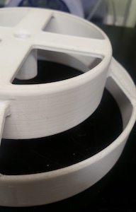
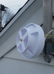
This is an example of using the aforementioned methods to print this item. This item is sitting upsidedown from how it was actually printed.
|
|